okko's gardening blog

Things I made

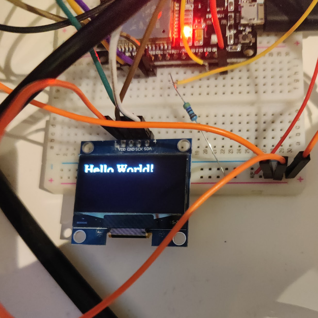
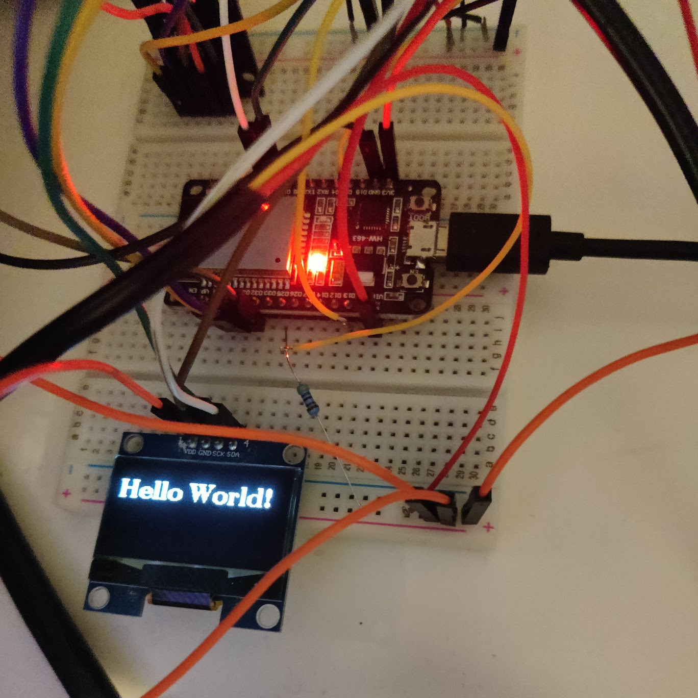
So the next task was to figure out the rotary encoder. The plan with it was to eventually have it control some basic settings of the system. For instance changing what would be displayed on the screen.
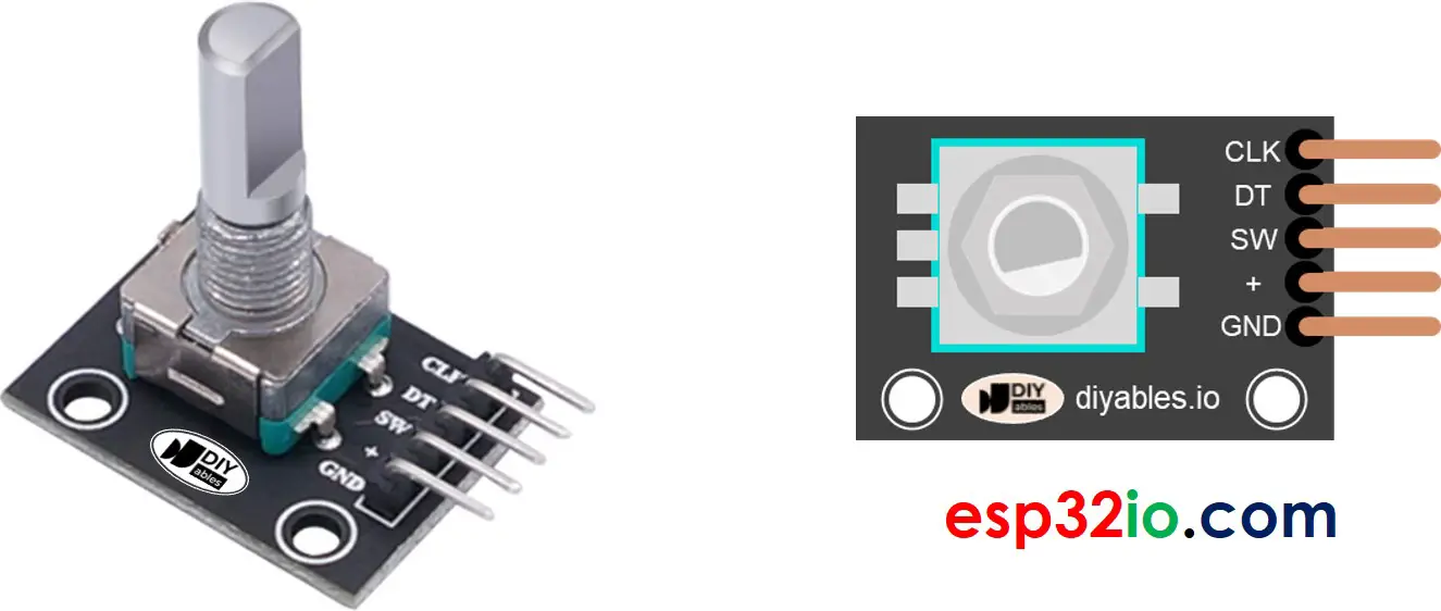
Image of generic rotary encoder

Image from esp32io.

In most cases though it would make sense to control the ESP32 over wifi from my phone. The ESP32 could create a wlan network I could connect to with my phone and open a website to update the settings. But the web based stuff will be just a plan for the future.

I was following some tutorial, that adviced to use the EzButton library. I tried it out and got it quickly working. However, I found the input to be sort of slow and a little unrealiable. This might have been due to a too high debounce time or that the library was maybe not inteded for rotary encoders. Or it might have been something else in the code I was doing wrong.

In any case I decided to look for a different library and found this RotaryEncoder library that seemed to be quite well thought out. Probably most importantly the examples had a code snippet for adding a interrupt for listening to changes in the encoder position.

IRAM_ATTR void checkPosition() {
  encoder->tick(); // just call tick() to check the state.
}


void setup() {
    attachInterrupt(digitalPinToInterrupt(PIN_IN1), checkPosition, CHANGE);
    attachInterrupt(digitalPinToInterrupt(PIN_IN2), checkPosition, CHANGE);
}

(You can see the full example code here: Github)

I got the hardware interrupts working quite quickly and now the input was much more reliable. I noticed that if I rotated the encoder in one direction and rotated it in the opposite direction, the first step in the opposite direction was not registered. Other than that there were no problems with it and the push button seemed to work nicely too.

Now the next thing would be to make the programmable led strip work. But that will have to wait for now since that needs some extra setup. After I get it working it would be time to try to integrate these four components into a full system.

My initial plan is to get this done in time for May 1st like I mentioned in part 1, but I will need some time to figure out how to attach everything to the overalls in addition to sowing at least 50 clothes patches into them. The unfortunate part is that ordering the overalls has taken my student organization an unusally long time.

I also have an ESP32 camera development board, so I would ideally use that so I could also snap pictures during events really nicely. One idea ir to make it take a picture every 30 minutes to an SD card. Luckily I have already gotten the camera to work once.

For those interested I have released the code as open source at codeberg.

Motivation

For some background for the project let me tell you about Finnish student culture.

Student boilersuits (sometimes called overalls) are very popular in Finland and everyone customizes them to mave them look and feel like their own. Now before starting my computer science studies at the University of Helsinki my dad showed me his old student boilersuit with all the gadgets he had put on it: EPROMS, LEDs and all kinds of electronic components. Now he did study electrical engineering so it makes sense he had that sort of things attached. And of course none of the components were wired to anything: just props.

A picture of a student boilersuit Photo from Wikipedia

So then naturally I was thinking I needed to go full tryhard mode if I wanted to make my overalls better than his and naturally that could only mean doing the same but actually wiring all the components together to make some kind of Iron man suit for myself.

Now two things are going to give me an advantage here. First, most electrical components can nowadays be bought for relatively cheap online. And second the help of my dad.

Getting started

Now for the actual implementation. The obvious choice was to go for an ESP32 microcontroller and attach stuff to it. That way I could control everything nicely and we already had some ESP32s lying around. First I decided to get a 128x64 pixel OLED screen, a temperature sensor, a rotary encoder and a strip of programmable LEDs all working. This would make up the version one of the project once I made a cohesive system out of these components

I first tried to get the OLED screen to work but I completely failed at it at first and after playing around with some Adafruit library for a few hours I decided to give up with the screen and start off simpler. The next day I followed a random nerd tutorials tutorial for setting up the temperature sensor which ended up being really simple.

Now since getting the temperature sensor working took me only approximately 15 minutes I got back to programming the OLED screen. I asked my dad which library he had used to make a similar screen work and he linked me this u8g2-library. Now with the right library I got some text on the screen quite quickly.

A picture of a small OLED screen connected with wires displaying text "Hello World" partially

However, the text was vertically split so that the bottom part was not rendered. This was because I had changed the rendering mode to 2 pages while taying to get it to work. In this mode each chunk of the screen was written individually, meaning to turn the entire screen white the code would have to loop around 3 times until all the screen data had been sent from the microcontroller's memory. Now since the ESP32 has a good amount of memory I simply changed the rendering mode to full, meaning the whole screen buffer would be always in memory. Now the text appeared on the screen correctly.

A picture of a small OLED screen connected with wires displaying text "Hello World" completely

In the next part I will tackle the rotary encoder and maybe the LED-strip. Now we will see if I can manage to get this in time for May 1st (a big day for all students in Finland). I should have plenty of time, given I have been planning this since August.